🔍 Introduction
Custom cable assemblies are essential in today’s advanced technologies—from robotics and medical devices to AI servers and industrial automation. Off-the-shelf cables often fail to meet the performance, durability, and space constraints required in modern systems.
This guide walks you through how to design a custom cable assembly in 2026, covering materials, electrical performance, mechanical reliability, and manufacturing considerations.
⚡ What Is a Custom Cable Assembly?
A custom cable assembly is a tailored interconnection solution designed to meet specific electrical, mechanical, and environmental requirements.
It typically includes:
- Conductors (signal, power, or hybrid)
- Insulation and shielding
- Connectors and terminations
- Outer jacket and strain relief
🧩 Step 1: Define Application Requirements
Start with a clear understanding of your application:
🔸 Electrical Requirements
- Voltage and current ratings
- Data speed (Mbps / Gbps)
- Signal type (analog, digital, RF)
🔸 Mechanical Requirements
- Flexing, bending, or torsion
- Installation space constraints
- Cable routing path
🔸 Environmental Conditions
- Temperature range
- Exposure to chemicals, oil, UV
- Moisture or IP rating requirements
👉 Example: A robotic arm requires high-flex, torsion-resistant cables, while a medical device needs biocompatibility and precision shielding.
🔌 Step 2: Choose the Right Conductor
The conductor is the core of the cable.
Key Factors:
- Material: Copper (standard), silver-plated (high-frequency), tin-plated (corrosion resistance)
- Stranding: Fine strands improve flexibility
- Gauge (AWG): Determines current capacity
👉 Tip: For high-flex applications, use ultra-fine stranded conductors.
🧲 Step 3: Design for Signal Integrity
High-speed systems require careful electrical design.
Considerations:
- Controlled impedance (critical for LVDS, USB, HDMI, etc.)
- Crosstalk reduction (twisted pairs, shielding)
- Signal attenuation over length
👉 Use:
- Twisted pairs
- Individually shielded pairs
- Low-loss dielectric materials
🛡️ Step 4: Select Shielding Strategy
Shielding protects against EMI and ensures stable performance.
Options:
- Foil shielding → high-frequency protection
- Braided shielding → flexibility and durability
- Combination (foil + braid) → best overall performance
👉 For high-speed and harsh environments, hybrid shielding is recommended.
🧴 Step 5: Choose Insulation & Jacket Materials
Material selection impacts durability and compliance.
| Material | Key Benefits | Typical Use |
|---|---|---|
| PVC | Cost-effective | General applications |
| TPE | მოქ flexible, مقا chemical resistance | Robotics |
| PUR | Abrasion + oil resistant | Industrial automation |
| PTFE | High temperature, low loss | Medical / RF |
👉 Match material to environment, not just cost.
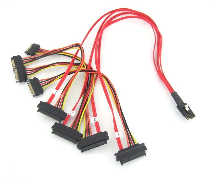
🔗 Step 6: Connector Selection
Connectors must match both electrical and mechanical needs.
Key Considerations:
- Mating cycles
- Locking mechanisms
- Size and pitch
- Compatibility with standards (USB, HDMI, etc.)
👉 Poor connector choice is a leading cause of failure.
🔧 Step 7: Strain Relief & Mechanical Protection
Mechanical stress is one of the biggest failure risks.
Solutions:
- Overmolding
- Heat shrink tubing
- Cable glands
👉 Always protect transition points between cable and connector.
🔄 Step 8: Flexibility & Motion Design
For dynamic applications:
- Maintain proper bend radius
- Use high-flex materials and conductors
- Design for millions of cycles
👉 Critical for robotics and automation systems.
🧪 Step 9: Testing & Validation
Before mass production, validate performance:
Electrical Tests:
- Continuity
- Insulation resistance
- Signal integrity
Mechanical Tests:
- Flex life testing
- Pull force testing
Environmental Tests:
- Temperature cycling
- Moisture resistance
🏭 Step 10: Manufacturing Considerations
Design for manufacturability (DFM):
- Simplify assembly steps
- Use standardized components where possible
- Ensure consistent quality control
👉 Work with an experienced manufacturer to optimize cost and lead time.
🚫 Common Design Mistakes
- Ignoring EMI shielding requirements
- Using standard cables in dynamic applications
- Poor impedance control
- Underestimating environmental factors
- Weak strain relief design
📊 Quick Design Checklist
✔ Define electrical + mechanical requirements
✔ Select appropriate conductor and insulation
✔ Optimize shielding for EMI
✔ Choose reliable connectors
✔ Design for flexibility and durability
✔ Validate through testing
🚀 Conclusion
Custom cable assembly design in 2026 requires a holistic approach—balancing electrical performance, mechanical durability, and environmental resistance.
By following a structured design process, engineers can create cable solutions that deliver:
- Reliable signal transmission
- Long service life
- Compliance with industry standards
For advanced applications like robotics, medical devices, and high-speed systems, customization is the key to performance.